No products in the cart.
Payment methods accepted
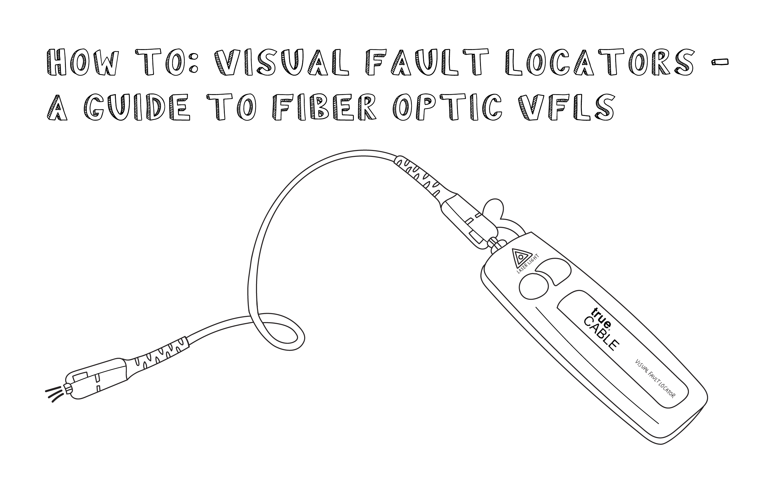
Written by Ben Hamlitsch, trueCABLE Technical and Product Innovation Manager RCDD, FOI
Struggling to identify faults, validate polarity or ensure quality mechanical connector terminations in your fiber optic cables? Visual Fault Locators (VFLs) are a valuable tool that make troubleshooting fast and efficient. Let’s dive into everything you need to know about mastering VFLs. In the realm of fiber optics, efficiency and precision are paramount. Fiber optic cables demand flawless functionality to ensure the smooth transmission of data. Diagnosing issues in these cables can often feel like solving a complex puzzle—that is, unless you have the right tools. One such basic test tool, which should be in every installer's tool box is the Visual Fault Locator (VFL) a small yet powerful device designed to help troubleshoot challenging fiber cable issues. Whether you’re a seasoned technician or a fiber enthusiast, a VFL is the first step to make your life easier in troubleshooting a fiber optic cabling issue.
We will be explaining what The VFL’s primary purpose is, and how best to use it. Below are some key use cases for a VFL. This article will focus on:
A Visual Fault Locator which can be also called visual fault identifier (VFI), fiber fault locator, fiber fault detector, etc., is a visible red laser light designed to inject visible red light energy into an optical fiber. Using a VFL to diagnose issues can save time and cost when diagnosing an issue. Throughout this article we will be referring to a Visual Fault Locator as a VFL for short.
trueCABLE has created a video companion for this blog that helps to further educate on this topic. Please take a look…but be sure to come back here and continue reading as the written blog adds even more information.
First let's look at some of the key features of a VFL. There are many flavors of VFL’s, and they range in laser output, range, and in some cases wavelength range.
Not all VFLs are created equal. When selecting a VFL, here are some key features to consider:
Visual Fault Locators (VFLs) operate in the 630-670 nm range, producing a highly visible red light. This specific wavelength is critical because it provides maximum visibility to the human eye, allowing technicians to quickly identify breaks, bends, or faults in the fiber. If a VFL does not use visible red light, it is not recommended for use, as it may compromise the efficiency of diagnostics. Additionally, many counterfeit products on the market may lack proper wavelength specifications or safety standards, potentially leading to unreliable results or even safety risks. Using a certified VFL ensures both accuracy and adherence to safety guidelines.
Ensure your VFL is operating in the 630-670 nm range using a red visible light.
VFLs are highly effective for distances up to 4 km in singlemode fibers and 3 km in multimode fibers. This range makes them versatile for a wide variety of applications, from short fiber patch cords to longer cable runs in telecommunications. The ability to pinpoint faults over such distances minimizes the time and effort required for troubleshooting, increasing efficiency in the field. Relying on VFLs with verified range specifications ensures they perform reliably under diverse conditions.
A max distance of 4km for SM and 3km for MM is sufficient for most applications.
High-quality VFLs are designed to support common connectors such as SC, ST, FC, and LC, often with the use of an adapter. This universal compatibility makes them essential tools for technicians handling a wide range of fiber optic systems. Using a VFL that aligns with standard connectors reduces the risk of damage during testing and ensures consistent results across different systems.
Purchase a VFL that works with most common connectors SC and LC
Standard VFLs utilize Class II or Class IIIa lasers, and typically are 5mW or less which are safe for use when proper precautions are taken. These laser classes are specifically chosen because they balance safety with effectiveness, emitting enough power to identify faults without posing significant risks to the user or the fiber system. Always confirm the laser class when purchasing a VFL to avoid counterfeit or substandard devices that could present safety hazards.
Class II or IIIa lasers are standard, offering safe yet effective performance.

Note: No need for 30mW or 50mW VFL’s Why?
Many VFLs offer both continuous wave and pulsing modes, providing flexibility for diagnostics. The continuous wave mode is useful for identifying persistent issues like fractures or misalignments, while the pulsing mode is better suited for locating intermittent faults.

We are now going to look at 5 key ways in which to use a VFL for identifying and troubleshooting a fiber network.
One extremely helpful way to diagnose fiber continuity problems is by using a VFL. Fiber continuity verification with a VFL is a simple, cost-effective, and reliable method to ensure fiber optic cables are functional and ready for optimal performance. Fiber continuity verification using a Visual Fault Locator (VFL) is a straightforward, budget-friendly, tool used in the field of fiber optics. Continuity verification ensures that fiber optic cables are not only physically intact but also capable of transmitting light signals guaranteeing optimal performance for data transmission and other applications.

A high-loss bend occurs when a fiber optic cable is bent beyond its minimum bend radius, causing significant signal attenuation or loss. A high-loss bend in a fiber optic cable occurs when the cable is bent excessively, this is called macro bending exceeding its minimum bend radius. There is another type of bending called micro bending and this is more internal to the fiber cable. See Macro and Micro bending to learn more. This overbending causes a significant reduction in the optical signal's power, referred to as attenuation or loss. The severity of the signal loss depends on factors such as the bend's tightness, the wavelength of the light transmitted, and the type of fiber optic cable used.
How does it work? The light travels along the fiber's core, and if there is a high-loss bend, a significant portion of the light will escape from the cable at the bend point. This escaping light is visible to the naked eye. In the event of a bend loss there may still be light at the far end of the cable but the light most likely will be faint and harder to see. Once the bend is identified it can either be straightened out or the cable can be rerouted to eliminate the high-bend loss. When it comes to Bend Insensitive fiber it takes a lot for a high-bend loss to occur so if you are seeing light escaping from the fiber cable when tested it may be a severe bend or a break or crack in the cable. If this occurs it is always a good idea to do some further troubleshooting using a OTDR to test the cable for loss and reflection over all.
This is also true if the cable has been cracked or broken. However in the case of a cracked or broken fiber there will be significant light leakage at the break or crack point, and in many cases there will be no light at the far end of the cable.
The VFL's ability to visually pinpoint the location of a high-loss bend, break or crack makes it an essential tool for fiber optic cable installers and technicians. By quickly and accurately diagnosing the issue, the VFL enables efficient repair and restoration of the fiber optic link, minimizing downtime and service disruption.

One way to connect a fiber optic cable is to terminate the cable end using a field terminated mechanical fiber optic connector. These connectors require alignment of the cable cores within the connector. These connectors have a small fiber stub in the connector. When these two fiber cores meet in the connector a type of gel called index matching gel is also in each mechanical connector.. The gel matches the refractive index of the fiber cores. This gel ensures alignment and reduces fresnel reflection and ensures more light is transmitted across the mechanical splice, enhancing signal strength and quality. However poor core alignment, contamination, or improper technique can lead to signal loss or reflection. This is where a Visual Fault Locator (VFL) can be used to help identify and resolve these issues, improving the quality and performance of your mechanical splices.

Testing fiber optic cable polarity ensures that the transmit (Tx) and receive (Rx) signals are correctly aligned when connected to a network switch, SFP or fiber adapter. This is critical for proper data transmission in duplex and multi-fiber systems. A Visual Fault Locator (VFL) can help verify this polarity by sending the visible red laser light through the fiber and tracking its patch to the other end of the fiber cable connector.
To test polarity with a VFL, first, connect the VFL to one end of the fiber optic cable using the appropriate connector. Turn on the VFL, setting it to continuous mode for a steady light output. At the opposite end of the fiber, observe which connector emits the red light. In a correctly configured fiber pair, the light should exit from the expected corresponding Rx port. If no light is visible or if the light appears in the wrong location, the fiber polarity may be reversed, crossed, or broken. This method is especially useful for quickly diagnosing polarity issues in patch cords, MPO/MTP cables, and structured cabling systems. If an issue is detected, the fiber connections may need to be swapped or reconfigured to ensure proper Tx-to-Rx alignment.
Below are two illustrations of what to look for when testing for polarity:
In this first image when we send light down the Transmit (TX) end of the fiber we should see it coming out the Receive (RX) side of the cable. Most duplex fiber patch cables will indicate this on the connector duplex clip with A-B and B-A or you may see a TX-RX and RX-TX to indicate the polarity.
Image shows light transmitted on TX and exiting on TX this is incorrect polarity!

Image shows light transmitted on TX exiting on RX this is correct polarity!

Below are the the basic steps to using a VFL to test a fiber optic cable and connector:
This is a very important step to follow. Dirt dust and oils are a large part of fiber optic system failures and can cause major problems when a connector is dirty and may even cross contaminate the fiber, transceiver or bulkhead the dirty fiber is interfacing with. For more information see Cleaning fiber Optic Endfaces. This will help in understanding the importance of this often overlooked step in fiber installation.
Photo 7
Attach the VFL to one end of the fiber cable using the correct connector type. The default ferrule size is 2.5mm for SC/ST/FC type connectors. For LC connectors, use an adapter if necessary. Ensure the connection is snug to avoid light leakage.

Turn on the VFL and select the appropriate mode. Most VFL’s have two modes: continuous or pulsing mode. Toggling the button on the VFL will allow you to switch between modes.
Continuous wave mode for identifying constant issues such as breaks or poor splices.
Pulsing mode for making it easier to locate faults over longer distances or in low-visibility environments.

No Light at the Far End:

Light Leakage Along the Fiber:

A Visual Fault Locator (VFL) is a powerful tool for identifying fiber optic faults, but improper use can lead to inaccurate results or even equipment damage. One of the most critical mistakes is using a VFL on active fibers—fiber optic cables that are already carrying live signals. Doing so can not only damage the VFL itself but also interfere with data transmission, potentially causing network issues. Always ensure the fiber is disconnected from any active network equipment before testing.
Another common mistake is skipping proper cleaning of fiber connectors before using a VFL. Dirt, dust, or oil on the fiber ends can scatter the visible red light, making it difficult to pinpoint actual faults. This can lead to misinterpretation of results or unnecessary troubleshooting steps. Additionally, using the wrong power level can cause problems—excessively high power can potentially damage the fiber, while too little power may not effectively detect faults. Most VFLs operate within safe limits, but always verify that your device is appropriate for the fiber type and length you’re testing.
Finally, ignoring safety precautions is a significant risk when using a VFL. The laser emitted by a VFL, while classified as low-power, can still be harmful to the eyes. Direct exposure can cause retinal damage, so never look directly into the fiber end when the VFL is active. Use proper protective equipment if necessary and follow industry best practices to ensure a safe testing process. By avoiding these mistakes, technicians can use a VFL more effectively, ensuring accurate troubleshooting while protecting both equipment and personnel.
One of the most important precautions is safety. Fiber optic safety cannot be over stated. It is important to always wear protective eyewear designed for laser work. Although most VFLs operate at a low power level, prolonged or direct exposure to the laser beam can still cause eye damage. Never look directly into the VFL’s laser light or the end of a fiber optic cable when the VFL is active. Even reflections can be harmful, so always handle fiber ends with care and use indirect observation methods.
Before using a VFL, disconnect the fiber from any active network equipment to prevent signal interference and avoid potential damage to the VFL or other connected devices. Additionally, when the VFL is not in use, store it in a safe, secure location to prevent accidental activation. Many VFLs come with protective caps or locking mechanisms—always use them to avoid unnecessary laser exposure.
In summary, Visual Fault Locators (VFLs) are excellent tools for fiber optic troubleshooting, offering a simple yet effective method for identifying faults, validating polarity, and ensuring high-quality mechanical splices. VFLs can help technicians quickly pinpoint breaks, bends, and misalignments within fiber optic cables, saving both time and cost.
This article has covered the essential aspects of VFLs, including their key features, such as wavelength range, laser output, range capabilities, and connector compatibility. We also provided a step-by-step approach to using a VFL effectively, ensuring accurate diagnosis and minimizing common mistakes. Additionally, safety precautions were emphasized to protect both technicians and fiber optic components from damage.
Selecting the right VFL is crucial for efficient fiber optic maintenance and repair. By understanding the different modes, power levels, and best practices for troubleshooting, technicians can optimize their troubleshooting and enhance the reliability of fiber networks. Whether you are a seasoned professional or new to fiber optics, a VFL is a must have in your toolkit.
Ready to simplify your fiber optic troubleshooting? Explore trueCABLE’s range of high-quality fiber optic tools, and take the guesswork out of your installations!
HAPPY NETWORKING!
trueCABLE presents the information on our website, including the “Cable Academy” blog and live chat support, as a service to our customers and other visitors to our website subject to our website terms and conditions. While the information on this website is about data networking and electrical issues, it is not professional advice and any reliance on such material is at your own risk.