


Future Proofing Your Network for 10G Internet
Written by Don Schultz, trueCABLE Senior Technical Advisor, Fluke Networks Copper/Fiber CCTT, BICSI INST1, INSTC, INSTF Certified
Get ready for it! A recent discussion with a ComCast installation technician revealed some rather interesting news. ComCast, along with other Internet Service Providers, are developing 10G (that is 10 Gigabit) Internet over coaxial cable. Yes, you heard that right--coaxial cable. Now, if you were like me, you have likely assumed this high bandwidth service would take place over fiber optic and I can assure you that it will get there too. What took me by surprise was this was happening over the regular old coaxial cable that we have all been used to seeing.
Well, that puts a new spin on things, doesn’t it?
That ties in with a very recently released product from trueCABLE, our Cat6A Direct Burial Shielded Ethernet cable. If you intend to bury bulk Ethernet cable, it will pay to use the stuff that will be future proof. The thing is, that future is not too far off. Let’s face it, trenching in and running Ethernet cable and putting up with possible underground obstacles is just not what most of us would term “fun”. Well, I would term it “fun” but I am a bit weird in a nerdy sort of way.
This development of 10G over coaxial also ties in with trueCABLE’s recent drive to demonstrate the best way of terminating solid copper Ethernet bulk cable. There is the “right” way, and there are ways that will seemingly work, but likely cause you issues at such high speeds.
Achieving 10G networking is not as simple as having 10G Internet. It is also not as simple as having Cat6A cabling. There is more to it. In this blog we will cover:
- Ethernet switching technology to take advantage of your ISP speed
- LAN layout strategy to get as much as possible from your investment
- Cabling and terminations necessary to achieve LAN speeds of 10G--reliably!
What we will not get into for this blog is the actual termination procedure as this has been covered in depth. Instead, the focus will be on getting the whole system correct. We are looking at the bigger picture today!
Considering there are quite a few ways to get from A to B and each network installation is a bit different due to a lot of reasons, we will cover a specific situation that can be extrapolated across most home or small business installs. If this is a big business situation, then you likely already have really expensive managed enterprise grade 10G over copper switches…this blog would not be aimed at you. So, in this scenario we will propose a two structure situation as follows:
- Main house where the Internet comes in
- In-law arrangement, in a separate structure on the property (basically any external structure is included here)
- To get Internet over to the separate structure, you need to trench in an outdoor/direct burial style Ethernet cable. This could also be an aerial run, too. More on that later.
- You wish to maintain a 10G “backbone” between the two structures
- You will also need interior Ethernet cable to wire up the inside of the structures
- You don’t want to blow a ton of money, though
To be clear, your all-in-one cable modem likely already comes with a four port switch built in. We will assume that is not going to be enough. If you opted for 10G Internet, then you have bigger plans than four devices!

- Cable modem, with coaxial cable female attachment port (near bottom)
- Four port Ethernet switch (which should be 4 x 10G ports)
- WiFi access point built in
- Routing and Internet firewall (for network security) built in
Switching Technology
So, let’s assume your friendly cable Internet installer just plopped the above combined cable modem/router/WiFi access point onto your desk and you are ready to get surfing at 10G! Will you actually get 10G inside your internal network (LAN) if you buy just any old additional switch? Sorry, but no. You also know that your WiFi signal will not reach over to the other structure on your property. WiFi is great for convenience, but comes with serious drawbacks such as range and structural interference that can play havoc with that range. WiFi has additional penalties such as EMI/RFI interference and no WiFi connection will be as stable and reliable as wired Ethernet--particularly between buildings. You will have to start running wire, so first what kind of switches should you buy?

Another factor to take into consideration is to be sure the switches you buy support what is known as NBASE-T. This means the switch, on all or certain specific ports, will support intermediate speeds between 1G and 10G. There are older Ethernet switches that support either 1G or 10G, but not 2.5G and 5G as intermediate speeds. Get the switch that supports the intermediate speeds. For example, if you don’t have 10G Internet but instead opt for 2.5G or 5G Internet you don’t want your switch to sabotage you. If your switch restricts you to 10G or 1G only, then you will be operating at 1G on your backbone in this scenario! The Netgear switch pointed out above supports NBASE-T on the two backhaul ports for just this reason.
- Cable modem router combo device (as supplied by your ISP, probably a monthly rental)
- Two switches with at least 2 x 10G Ethernet ports each, the rest are likely to be 1G Ethernet ports
LAN Topology - Conceptual Design
Getting your internal network up and running stops if you have no desire to extend your network into an outbuilding or if you don’t need more than 4 Ethernet ports. However, what would be the fun in that? We assume you will need more ports and you want to get 10G backhauled out to your outbuilding. For that, we will need to step back and draw out the design of the network. This is a simple network, but it is always a good idea to draw out what you want. This helps eliminate logical errors in your setup and helps you to visualize what your overall installation will look like. Here we go:

Don’t let the above diagram scare you. This an attempt at drawing out how the installation will look logically and with some physical elements tossed in for clarity. Here is what is going on with the diagram:
- There are two structures (house with detached garage for example)
- The main structure has the all-in-one cable modem WiFi combo device with a 10G Ethernet switch plugged into the combo device to extend the network
- For purposes of this exercise, you wish to wire up some wall outlets in both structures and install a remote PoE powered WiFi Access Point in the second structure along with PoE powered surveillance cameras at both structures
- The cable between the two structures is the Cat6A Shielded Direct Burial cable, and this cable is known as the backbone cable
- The backbone ALSO includes the three (yellow coded) Cat6A shielded factory pre-made patch cables. All of these connections will be into the 10G ports on the Ethernet switches and your all-in-one cable modem combo. This is your continuous 10G backbone to the Internet.
- The idea behind putting a stand-alone WiFi Access Point in the remote structure is you will still have good WiFi access when away from the main house/structure. If you make the WiFi network name and password the same as the all-in-one combo router device your smartphone can roam seamlessly between your two buildings as you move about the property.
So, this is quite a bit of information from just one picture! There is one more item we need to cover before we can get into the actual bits and pieces of this installation, and that would be a discussion around patch panels.
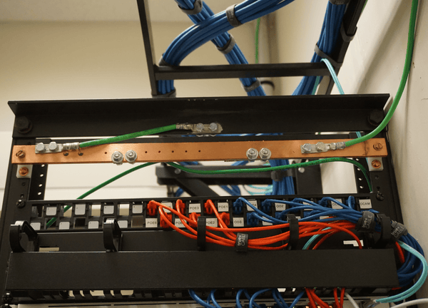
Patch panels organize and clean up your installation. They serve as the centralized attachment point for your Ethernet cable at the Ethernet switch end of the connection and radiate cabling outward to the final destination. Patch panels come in monolithic 110 punch-down style or modular keystone jack style. The end result in both cases is the same--an organized installation. These pictures are an example of a keystone jack patch panel in a telecom room that I installed recently:

Top view of patch panel. This is a keystone patch panel.
Front view of the keystone jack patch panel. Patch cables connect from there to the Ethernet switch.
Why might you want a patch panel? Quite simply, the tool-less style ones with 24 ports don’t cost very much and they centralize your cable. You don’t need a monster equipment rack to mount one. Patch panels meant for 19” rack mounting can also be mounted to a wall bracket above your Ethernet switch. Essentially it is a big frame to snap in your keystone jacks. The Category of the keystone jacks matters, but with keystone patch panels (especially shielded ones) Category does NOT matter--it is just a bracket with no logic built in. Here is an example of a shielded keystone patch panel that has no keystones in it:

Pretty simple, huh? The green wire is a bond/ground wire. We will talk about that later.
The second reason you will want to use one of these items is it will allow you to bond your shielded cable to ground. That is what the green ground wire is for. Connect the green ground wire to a properly grounded outlet (simply remove the center screw and screw the ring terminal to the top of the wall plate using the center screw) so you are bonded to your ground system in your home. If the green ground wire is not long enough to reach, then pick up some 10 AWG stranded green jacket THHN ground wire and crimp on a couple of ring terminals at both ends and replace the wire that comes attached to the patch panel out of the box. If you use 10 AWG you will be good up to six feet of reach. Don’t go over that!
So, here are more items to add to your shopping list we started above:
- Shielded keystone jack patch panel frame, 16 or 24 port, Category does NOT matter
- Wall bracket to mount the patch panel frame, 4U or 6U
- Extra rack mount shelf to mount switch and cable modem
- Surge protector for Ethernet
You can get this stuff as simple or as fancy as you like, and some of the choices are pretty amazing. It will really tidy up and make your install look super professional. The correct cage nuts and screws will come with these items, so all you need is a screwdriver and a way to mount the rack to your wall. I suggest a painted plywood backboard to help with weight.
Here is an example of a residential setup I did. In this case, I made use of a horizontal rack unit and a vertical mount bracket for a couple of big managed switches. Your setup will likely look similar to this:


This residential setup is making use of:
- Shielded 24 port patch panel, tool-less
- Shielded Cat6A keystone jacks, tool-less trueCABLE brand
- Shielded Cat6A patch cables, 18” length
- In-line surge protector that is protecting the expensive switching equipment from ESD and near lightning strikes on an aerial (overhead) Ethernet cable run
- Small bonding busbar that is used to bond the surge protector and shielded patch panel wires to ground, all at once
- A ½” plywood panel, painted white, is used as a backer over the drywall to provide for a sturdy mounting point
- The Ethernet switches and a other equipment are mounted vertically in a rack-like wall mount
As you can see, you can get as advanced and fancy as you like. I gave you two detailed examples of different styles of how to mount patch panels and other equipment, so you can spend as little or as much as you want to.
A question may arise about shielded tool-less (or even the punch down style) patch panels: “Can I use unshielded cable and unshielded keystones with a shielded patch panel?” Absolutely! In fact, this ensures that you have the flexibility to run shielded cable and unshielded cable as necessary. Just be sure your shielded patch panel is bonded to ground correctly for your shielded runs and you are good to go.
Cat6A Terminations
When you install a Cat6A cabling system designed to handle 10 Gigabit networking, you need to use the following:
- Cat6A Ethernet cable for all permanent runs (solid copper)
- Cat6A stranded copper patch cable (for patching equipment together)
- Cat6A keystone jacks
- Cat6A patch panel (if it is a monolithic style 110 punch down panel)
There are a number of ways of terminating Ethernet cable, and you will want to avoid using RJ45 8P8C connector plugs unless absolutely necessary. There are only two areas where RJ45 8P8C plugs are acceptable:
- At the ends of factory pre-terminated patch cable (which means YOU did not terminate those plugs, a factory did)
- At a single end of a MPTL link (Modular Plug Terminated Link). MPTL links are keystone to RJ45 or monolithic patch panel to RJ45. These are typically seen in use with PoE devices where the end point device (like a camera or WiFi Access Point) is designed in such a way that the physical housing will not accept a Field Termination Plug.
All that said, you will want to use a “rack to jack” strategy anywhere you can. That means all permanent Ethernet runs should be keystone to keystone (or patch panel to keystone) or secondarily use Field Termination Plugs that use keystone style mechanisms to terminate. This is critically important. See Terminating Pass-Through RJ45 Connectors onto Solid Copper Ethernet Cable -- A Really Bad Idea? for quite a bit of information around various terminations and performance.
You could, theoretically, skip using patch panels or keystones at all and simply use Field Termination Plugs everywhere and still maintain excellent 10G performance, but you rob yourself of flexibility and a professional looking installation. It will be a spaghetti mess, quite frankly.
Here are some pictures of the sort of terminations you want to use:
For unshielded installations:

Cat6A termination hardware. Two unshielded keystones (one punch down, the other tool-less) and a Cat6A Unshielded Field Termination Plug.
For shielded installations:

Cat6A termination hardware. A shielded tool-less keystone and a Cat6A Shielded Field Termination Plug.
If you elect to use a monolithic shielded Cat6A patch panel (110 punch down style) then this piece of equipment will look something like this:


Shielded 24 port Cat6A patch panel, 110 punch down. This example is from TrippLite.
Of course, alternatively you can use a shielded tool-less patch panel and simply snap in Cat6A shielded tool-less keystones as you require them. It is up to you.
Special Consideration for Lightning Prone Areas
Let’s take a look back at the one piece of equipment I didn't really get into before, which is the ESD/lightning protector. This piece of equipment should be used to protect shielded OR unshielded outdoor cable runs, especially runs exceeding 110 feet, in areas that see more than five lightning storms per year. If the run is overhead (an aerial run) between structures, then a ESD/lightning protector is all but required.

Tupavco ESD/Lightning protection for an aerial run. This is an outdoor version, but they come in indoor versions, too. I used an outdoor one because that is what I had on hand.
This device uses a “gas discharge tube” to instantly sever the Ethernet connection between your patch panel and expensive Ethernet switch in the event of a severe ESD/near lightning strike. It likely will not stop a direct hit (not much will), but it will help keep your equipment safe. This device should be installed inline before any Ethernet switches that are connected to that at-risk run! These devices must be bonded to ground. In the above picture, I have the shielded patch panel and ESD/lightning protection bonded to a small “bus bar” and that bus bar is then bonded to a properly wired and in-code AC outlet. For more information on this matter see When Lightning Strikes! Ethernet Data Cable and Lightning Protection.
For fun, here is what a commercial size bus bar looks like:

That is 6 AWG stranded ground wire with double lug terminals crimped on. The bar itself is ¼ thick, per code. All metal in this telecom room is bonded to this bus bar and runs to the building AC ground system.
Wrapping up, as you can see, installations can range from relatively simple to complex. What your particular installation will look like depends on how much equipment you have to connect and how professional you wish to be. My strong suggestion is to do it right the first time and not cut any corners. Remember, we are future proofing your system for 10G Internet!
HAPPY NETWORKING!!
trueCABLE presents the information on our website, including the “Cable Academy” blog and live chat support, as a service to our customers and other visitors to our website subject to our website terms and conditions. While the information on this website is about data networking and electrical issues, it is not professional advice and any reliance on such material is at your own risk.


